KEGCALC

FROM BUILD TO FIRST POUR

Get your taproom ready.

Choose a step below. Work from the fridge plan to your first pour, or jump straight to the help you need.

Plan your space & choose your fridge

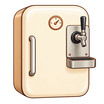
A garage-sale find, thrift-store gem, or vintage refrigerator can become a kegerator with real character. Start with a sound appliance that fits your kegs. A bargain stops being a bargain when it needs major refrigeration repairs or cannot support the load.

Before you bring it home

Open the door and smell it. Stale spills may clean up; persistent sour, moldy, or rotten odors can linger in seals and insulation. Look for mold, standing water, rust, cracked liners, and damaged door gaskets. Heavy perfume or deodorizer is a reason to inspect more closely. If the smell persists after cleaning and drying, keep looking.

Make sure it actually cools. A working light or humming compressor is not proof. Ask the seller to run it ahead of your visit and check it with a thermometer; ideally, verify it reaches and holds your intended serving temperature over several hours. Check the cord and door seal, and budget for repairs before buying. A plug-in temperature controller does not fix a refrigeration fault or a failed internal thermostat that keeps the compressor from running.

Measure the usable shape, not the advertised capacity

Measure the flat floor area, the narrowest door opening, and the height above the keg with its coupler and hose attached. Allow space for the CO₂ bottle and regulator if they will live inside. Door bins, drawers, shelves, and the compressor hump all subtract from usable space. Bring cardboard circles cut to your actual keg diameters and check the layout with the door closed.

The floor matters as much as the footprint. Many modern fridges have a sloping or stepped plastic lower liner that makes room for the compressor behind it. That is a poor starting point for a heavy keg: it may rock, sit crooked, or concentrate weight on unsupported plastic. Avoid these for a straightforward conversion unless you can provide a properly supported, level platform without losing the headroom you need. A board over a weak liner does not automatically make the structure strong enough.

Where will the CO₂ bottle go?

Inside the fridge is ideal when it fits: everything stays together and you avoid a separate hole for the gas line. Allow room for the bottle, regulator, and hose connections, and secure the bottle upright.

An external bottle is a useful space-saving option. It requires a dedicated hole for the CO₂ line or a suitable existing pass-through. Before drilling, verify the entire route is clear of refrigerant tubing and wiring. Protect the hose from sharp edges with a suitable grommet or bulkhead fitting, seal the opening, and secure the bottle upright outside.

Moving the bottle outside may leave room for two sixth-barrel craft-beer kegs, depending on the fridge’s usable floor area and headroom. A CO₂ manifold with individual shutoffs and check valves can feed both kegs from one regulator. Both beers must suit the same storage and serving temperature because they share one refrigerated space. Choose beers with compatible temperature targets. A basic manifold supplies both kegs at the same pressure. A dual-output regulator or a secondary regulator bank with two independently regulated outlets can be helpful: each beer can have the pressure needed for its carbonation target at that shared temperature. A manifold with shutoff valves alone cannot set two different pressures, and separate regulators do not create separate temperature zones. Calculate pressure and beer-line length for each beer individually. Each keg still needs its own compatible coupler, beer line, and faucet.

Compare CO₂ bottles →
Find a regulator, manifold, and couplers →

Which refrigerator layout works?

Vintage freezer-on-bottom: A 1970s-era model with a flat, structurally sound steel refrigerator floor is an especially appealing find. That arrangement offers a stable keg base and puts the refrigerator compartment—and your taps—higher for a comfortable pour. Check the actual model: age alone does not guarantee a steel floor, and steel still needs inspection for rust and support. Remember that loading a full keg onto the higher floor takes more lifting.

Side-by-side: Usually a poor choice for a full-size keg because the refrigerator compartment is too narrow. Some can fit smaller homebrew kegs, but measure the clear width, door opening, and fittings before committing.

Freezer-on-top: Can work, but the lower refrigerator door can leave the tap uncomfortably low. Check whether you can mount the faucet high enough on the fridge door—or at a verified clear location on the side—while leaving room for the shank and hose inside. Check the bottom’s strength after removing drawers; a plastic drawer cover or glass shelf is not a keg platform.

A chest freezer with a tower

A chest freezer converted for draft service is often called a keezer. Use a compatible plug-in temperature controller to hold it at beer-serving temperature instead of freezing. Match the controller to the appliance’s electrical load and follow its compressor-delay instructions. Measure the stabilized beer temperature rather than relying only on the controller display.

Plan the keg layout around the compressor hump and leave room for couplers, tubing, and the closed lid. Mount a draft tower on a suitably reinforced lid only after verifying that the drilling and fastener locations are clear of wiring and refrigeration components. Keep the tower’s beer lines insulated and plan cold-air circulation into the tower to reduce warm first pours.

Check that the lid can open with the tower attached: the tower and faucets need clearance behind the freezer, and the lines need enough slack without kinking. You will also need to lift full kegs over the rim. A wooden collar with shank-mounted faucets is another option if a moving tower or lifting clearance does not suit your space.

Browse temperature controllers →
Browse draft towers →

Check the pour before you drill

Stand where you will serve, hold a glass at the proposed tap height, and check clearance for the handle, drip tray, and open door or lid. Confirm the floor supports the full keg weight and the appliance has its required ventilation and suitable ambient conditions for the garage or room. Verify the complete drilling path is clear of refrigerant tubing and wiring before making even a pilot hole.

Further reading: Beverage Factory conversion and keg-fit guide; Brew Your Own chest-freezer conversion. Check the appliance manufacturer’s instructions for your specific model.
Mount the faucet

Start on the inside of the door

Choose a flat area of the inner liner where the shank’s mounting washer and nut can sit squarely. Avoid molded shelves, ribs, curves, and plastic bump-outs—even if the same spot looks perfect from outside. Check the space behind it with the keg in place and the door closed: the shank, fitting, and beer line must clear the keg and leave room for a gentle hose bend.

Transfer the location to the outside using measurements from matching reference points. Check comfortable pouring height, glass and drip-tray clearance, and room to operate the tap handle. For two faucets, leave enough space for the handles, mounting hardware, and your hands.

Choose the shank before the hole saw

A little extra shank can extend into the fridge; a shank that is too short will not work. Measure the complete door thickness at the mounting position and allow for any backing plate, washers, and full mounting-nut engagement. Check the manufacturer’s usable mounting length or maximum wall thickness, not just the advertised overall shank length. Extra length is fine only if the rear fitting and hose still clear the keg when the door closes.

Match the hole to the shank’s outside diameter and installation instructions. The beer passage’s bore size is not the mounting-hole size. Our selected cutter is 15/16 inch; use it only when that opening suits your shank and its mounting hardware. The flange and rear washer need solid material to bear against. Do not oversize the hole just to make assembly easier.

One pilot hole, then cut from both sides

Unplug the appliance. Use the manufacturer’s information to verify that the entire drilling path is clear of refrigerant tubing and wiring before making any hole. A pilot hole is for alignment, not for discovering hidden services. Do not assume a door or sidewall is clear.

Drill a small pilot hole straight through the door. Keep it aligned with the intended shank axis and sized to work with the hole saw’s pilot bit; an oversized pilot hole will not guide it properly. Check that the exit is in the flat inner area you planned before enlarging either opening.

Using the pilot hole as the common center, cut the outer metal skin with the 15/16-inch hole saw, then work from inside to cut the plastic liner. Cut each skin from its own side and remove the foam between the openings. This shallow cutter is not intended to reach through the entire insulated door in one pass. Support the door, wear eye protection, and follow the cutter’s speed and material instructions; avoid forcing the teeth or melting the plastic.

SALI 15/16-inch hole saw at Amazon (paid link) →
As an Amazon Associate I earn from qualifying purchases.

Fit it firmly without crushing the door

Remove debris and sharp burrs, then test-fit the shank. Install the flange, washer, nut, and any specified backing or spacer according to the shank instructions. Thin plastic and foam can compress: use suitable reinforcement where needed rather than tightening until the liner cracks. If a sleeve or spacer is required, its outside diameter may call for a different hole size—plan that before drilling.

Align the faucet upright and secure its coupling with the correct faucet wrench without overtightening. Connect the beer line with the proper fitting and seal, leaving slack for the door to open without pulling or kinking the hose. Close the door slowly to check clearance, then check for leaks when the system is connected and pressurized.

Compare faucet shanks →
Match the beer line, fitting, and clamp →

Reference: Kegco conversion instructions, pages 6–7, illustrate the flat inner location and pilot-hole method. Their kit uses different hole sizes; follow your own shank’s specifications.

Connect the gas & check for leaks

Start with the right connection

Secure the CO₂ cylinder upright, with its valve accessible. Use a primary regulator made for CO₂ and the cylinder’s valve connection; the common US draft-beer connection is CGA-320. Keep the cylinder valve closed while assembling. Follow the regulator’s instructions for backing off its pressure adjustment and closing its outlet before connecting it.

Why that little fiber gasket matters

The cylinder-to-regulator joint needs a seal between its mating faces. On a regulator designed for a loose washer, the correct CO₂ fiber gasket compresses between those faces to stop gas escaping. Without it, the connection can leak even when the nut feels tight. Use the exact washer type and size specified for the regulator; some designs use plastic rather than fiber.

For a loose-fiber-washer design, fit a fresh washer when changing or reconnecting the cylinder. Remove the old washer first—check that it has not stuck to either face. Do not stack washers or substitute a beer-line washer. Keep the mating faces clean and undamaged. On this face-sealed cylinder connection, the nut’s threads pull the faces together; they do not make the gas seal, so plumber’s tape is not a substitute for the gasket.

Does your regulator already have a seal?

Some regulators have a built-in O-ring or captive seal at the end of the inlet stem, inside the cylinder-connection nut. With the cylinder closed and the regulator safely depressurized and disconnected, inspect that face and check the model’s manual or parts diagram. A seated ring or captive sealing insert can indicate a built-in seal; do not decide from the brand or color alone.

If the manufacturer specifies a built-in seal with no separate washer, do not add a fiber washer on top. Check that the installed seal is present and free of cuts, flattening, or other damage. “Permanent” means reusable, not indestructible. Replace it with the specified part if damaged; do not compensate with extra washers or excessive tightening. If you cannot identify the seal arrangement, confirm it before connecting the cylinder.

Connect and pressurize

Attach the regulator using the manufacturer’s tightening instructions. Connect matching gas-rated hose and fittings from its outlet to the coupler’s gas inlet, or through a manifold to each keg. Secure barbed connections with properly sized clamps. Keep the faucet closed and check the coupler instructions before engaging it. Open the cylinder valve slowly and set the intended operating pressure according to the regulator instructions. Never raise pressure above the equipment’s rating to hunt for a leak.

A DIY soapy-water leak check

Mix a few drops of mild dish soap into a small cup of water, enough to leave a bubbly film. Avoid cleaners with bleach or ammonia. Commercial gas leak-detection fluid is another option, especially if your equipment maker specifies it.

With the assembled system pressurized, brush or dab the solution onto the outside of the cylinder-to-regulator joint, accessible gas fittings, hose ends, manifold connections, and coupler gas connection. Test each branch with gas supplied to it. Do not flood gauges, regulator vents, electrical parts, or the inside of any fitting.

Watch for bubbles that grow or keep forming. Foam left by the brush alone is not proof of a leak; continuing bubble growth at one spot is. Give small leaks time to show and check around the entire joint. No visible bubbles is a useful check, not a guarantee that every possible leak has been found.

If you see a leak, close the cylinder valve and safely release trapped pressure using the equipment’s instructions before loosening anything. Correct the seal or fitting, then pressurize and test again. Wipe away soap residue with a damp cloth and dry the parts afterward. Repeat the check after each cylinder change or gas-line alteration. Keep the area ventilated; CO₂ has no warning smell. If a cylinder valve itself leaks, stop using it and contact the cylinder supplier.

Browse regulators and gas connections →
Check hose and clamp compatibility →

References: Micro Matic regulator and seal basics; Taprite installation instructions; Micro Matic external leak-check guidance. Follow the instructions for your exact regulator and cylinder.

Connect & tidy the beer line

Start with the right hose and length

For a typical home kegerator, start with 3/16-inch ID × 7/16-inch OD beverage-grade vinyl beer line. Larger bores are specialized options, not an automatic upgrade. Match the hose to the fitting and calculate a starting length for your temperature, carbonation, and faucet rise before cutting. Keep the length needed to balance the pour; do not shorten it just to make the fridge look tidier.

Why we prefer Oetiker-style stepless ear clamps

For vinyl beer tubing on barbed fittings, a correctly sized stainless stepless ear clamp is our preferred choice. Its smooth inner band applies pressure evenly around the hose, without the slots and bulky screw housing of a common perforated automotive clamp. It makes a compact connection with fewer projections to catch neighboring lines. Oetiker is a brand; other manufacturers also make stepless ear clamps.

Choose the clamp’s working range using the hose diameter over the installed barb, not the hose’s inside diameter alone. Slide the clamp onto the hose before seating the tubing fully on the fitting. Position and close it with a proper ear-clamp pincer following the clamp maker’s instructions. The correct closing force matters; do not simply crush the ear as hard as possible. These clamps are single-use: replace one after cutting it off.

No ear clamps or crimp tool?

A correctly sized smooth-band stainless screw clamp intended for small soft tubing is a practical, reusable alternative. Choose a size close to the assembled hose diameter and tighten according to its instructions without cutting or flattening the tube. Avoid oversized, perforated automotive clamps that can bite into soft vinyl or clamp unevenly around their housing. A suitable smooth-band clamp can work well regardless of which store sells it.

Do not substitute zip ties for hose clamps at pressurized connections or use a clamp to make mismatched hose and barbs fit. If you use a compatible push-fit system instead, match the exact tubing outside diameter and follow its insertion instructions; that connection does not use an ear clamp.

Coil the extra line instead of trimming it away

Route the line with gentle bends from the coupler to the shank, then gather the slack into a broad, relaxed coil. Follow the tubing maker’s minimum bend radius and let the hose follow its natural curve. If it flattens, creases, or tries to kink, make the loops larger. Do not wrap it tightly around the coupler or pull sideways on a fitting.

Use two or three loosely fitted zip ties spaced around the coil to hold the loops together. Close each tie only enough to keep the bundle organized: the tubing must stay round, with no dents or pinching. Reusable hook-and-loop straps are another easy option for keg changes. Trim zip-tie tails flush, taking care not to nick the beer hose.

Rest the coil neatly above the keg or on a suitable support inside the cooled space. Keep it away from freezing surfaces, fans, and door seals, and leave the coupler handle and pressure-relief valve accessible. Leave enough free line for the door to open and the coupler to be removed without tugging the connections. For two beers, coil and label each line separately.

Close the door slowly and check for trapped tubing. After cleaning the beer path and connecting the system, inspect every joint for leaks and confirm the hose remains round and unkinked. The zip ties organize slack; they should never squeeze the hose to control flow.

Where to fill your CO₂ bottle—and keep your own tank

Call local beverage-gas suppliers, welding or industrial-gas shops, fire-extinguisher service companies, and homebrew stores. Some fill cylinders on site; others send them out or only offer exchanges. Search for “beverage CO₂ refill” with your town or ZIP code, then confirm they handle your cylinder size and supply CO₂ suitable for beverage use.

If you bought a brand-new tank, ask for a refill of your own cylinder—not an exchange. An exchange means handing over your bottle and receiving a different filled one, which may be older or show more cosmetic wear. That can be convenient, but it is not the service to choose if you want to keep the new cylinder you paid for.

Before making the trip, ask: “Can you fill my customer-owned 5 lb or 10 lb CO₂ cylinder and return this exact tank to me? Is it filled while I wait or left for pickup?” Confirm beverage suitability, the total price, turnaround, and whether they accept its current test markings and valve. Tell the counter staff again that you do not authorize an exchange, and record the serial number or take a photo before leaving it.

Find a refill provider before buying a new bottle if keeping it matters to you. An older exchange cylinder is not automatically unsafe; condition and current inspection or test status matter more than shiny paint. If you choose an exchange, inspect what you receive and confirm the cylinder size, valve connection, and terms. If your own cylinder needs testing or repair, have the supplier explain the options before authorizing work or a swap.

Supplier references: Airgas beverage CO₂ information; an example of a fire-service company offering beverage CO₂ fills. Services and refill-versus-exchange policies vary by location; call ahead.

Find matching hose, fittings, and clamp sizes →
Browse clamps and crimp tools →
Calculate your starting line length →

Reference: Oetiker’s stepless clamp design. Follow the instructions for the specific clamp and tubing you select.

Chill your beer & control the temperature

Upgrade from the numbered plastic knob

A compatible external digital temperature controller can give you much clearer control than an old fridge’s “1–5” or “colder” knob. You set a temperature, read the probe temperature, and adjust the cooling behavior directly. It is particularly useful for vintage-fridge builds and for keeping a chest freezer above freezing. It still needs a working cooling system.

How the controller works

With a plug-in model, the controller plugs into the wall and the refrigerator plugs into its cooling outlet. A sensor inside the fridge tells the controller when to supply power and when to stop cooling. Match the controller’s voltage and compressor-load rating to the appliance, and confirm the fridge resumes cooling after power is restored. Some electronically controlled appliances do not suit this method.

Set the fridge’s own thermostat cold enough that it will call for cooling when the external controller supplies power. The external controller does not bypass the internal thermostat: if a fault keeps the compressor from starting, that fault needs repair. Keep the controller and its outlets dry and follow both manufacturers’ installation instructions.

Mount it outside and route the sensor

You can mount the controller on the back of the fridge if the location is dry, accessible, and clear of compressor heat, condenser tubing, and ventilation openings. Use a suitable existing mounting point or non-penetrating mounting method; do not drive screws blindly into the cabinet.

An existing suitable pass-through is the first option for the probe cable. If you need a new hole, unplug the fridge and verify the complete route is clear of refrigerant tubing and wiring before drilling. The rear wall is not automatically a safe place just because the controller is mounted behind it. Make the opening large enough to pass the probe without damaging it, protect the cable with a suitable grommet, and do not cut or splice the sensor cable unless its manufacturer permits it.

Seal the opening around the cable with silicone caulk suitable for the liner, insulation, and cable materials. Prefer a compatible neutral-cure product and let it cure fully according to its label before returning the fridge to service. The seal keeps warm, moist air out; it should not crush the cable or cover the sensing tip. Routing under a door gasket is another possibility only if the cable is not pinched and the door still seals properly.

Probe placement matters

Keep the probe away from a cold plate, cooling-air blast, or the door opening. For a reading that follows the keg more closely, secure it against the keg beneath a small insulating pad. If you choose a liquid buffer instead, verify the entire immersed part of the probe is rated for that use. Allow the keg to stabilize and compare with an independent thermometer; the displayed probe temperature is not automatically the beer’s exact temperature.

Give the compressor time between starts

Do not chase every tiny temperature change. The cooling differential sets how far the probe temperature rises before cooling starts again. On an Inkbird ITC-308, for example, a 38°F target with a 2°F cooling differential calls for cooling at 40°F and stops at 38°F. That describes the probe’s switching points, not a promise that every part of the fridge stays within that range.

The compressor delay sets a minimum wait before cooling can restart. Rapid stop-start cycling puts extra stress on the compressor and its starting components; refrigerant pressures need time to settle between starts. Enable the delay and follow the appliance manufacturer’s minimum restart interval. Do not set it to zero to get a faster response.

Inkbird’s example uses a three-minute delay: if cooling is requested again after only one minute off, the controller waits another two minutes before restarting. This illustrates the setting—it is not a universal recommendation for every fridge. Use your appliance’s required interval, and do not keep unplugging or resetting the controller to defeat the waiting period.

A very narrow differential, poor probe placement, or frequent door opening can still cause excessive cycling. Watch several cycles after setup and adjust within the equipment’s guidance. The delay protects the restart interval; it does not repair a failing compressor or guarantee sensible run times on its own.

Finally, let the whole keg reach a stable serving temperature before tuning pressure or judging foam. Keep the beer line and tower cold as well, and use the measured beer temperature in the calculator.

Browse temperature controllers →
Set pressure for your beer temperature →

Reference: Inkbird’s explanation of compressor delay and switching temperatures. Setting names and behavior vary by controller; check your model’s manual.

Set pressure & balance the pour

Set the regulator for the beer first

Use the beer’s actual, stabilized temperature and the brewer’s carbonation target to calculate regulator pressure. That pressure both maintains carbonation and pushes beer toward the faucet. Do not turn it down just to slow a fast pour: over time, the beer can lose carbonation. Too much pressure can overcarbonate it.

What “faucet pressure” means in this calculator

As beer flows, the line and fittings provide resistance, while an uphill run uses some pressure to lift the beer. Too little resistance can leave a fast, turbulent pour; too much can make the pour frustratingly slow. Warm beer, dirty fittings, and existing overcarbonation can also cause foam, so pressure balance is only part of the diagnosis.

The calculator’s Faucet pressure field is a modeling allowance for pressure remaining at the faucet inlet while pouring, after the estimated line and height losses. It is not a second regulator setting or the pressure of beer after it exits into your glass. A closed faucet does not have the same flowing pressure losses. The default is 2.5 PSI, a starting assumption rather than a universal ideal or a measured value.

Adjust the starting line length in the calculator

Open the pressure and beer-line calculator. Enter beer temperature and carbonation, choose your actual tubing, then open the advanced settings to enter faucet rise and adjust Faucet pressure. Use the units displayed next to each field.

Lower Faucet pressure → longer calculated line. The model assigns more of the available pressure to line resistance, which generally makes for a gentler, slower pour when that longer line is installed.

Higher Faucet pressure → shorter calculated line. Less pressure is assigned to line resistance, which generally permits a faster pour when that shorter line is installed. With the beer targets unchanged, this field changes the line estimate, not the recommended regulator pressure.

For example, changing the allowance from 2.5 to 1.5 PSI adds about 4.4 inches to the calculated length with the standard 3/16-inch vinyl preset at 2.7 PSI per foot, provided the calculation has a positive line-length budget. That is a model comparison, not a guarantee of a particular flow rate.

Test the physical setup, then make small changes

Changing a field on screen does not change the tubing already in your fridge. Start with enough line to test and trim gradually if needed; adding length back is harder. If the calculator reports insufficient pressure for the selected rise and allowance, review those inputs and the setup rather than treating a zero-length result as a usable installation.

With the keg and line cold, open a standard faucet fully and pour into a clean glass. Partly opening it to throttle the stream can create turbulence. If the pour is too fast after temperature and carbonation are confirmed, consider more line resistance. If it is too slow, first check for kinks, blocked fittings, or an incompletely opened coupler before shortening anything. A purpose-built flow-control faucet can provide additional adjustment according to its instructions.

Change one thing at a time, record the result, and let temperature and carbonation settle before judging another pressure change. Coiled line still counts toward total length. On a two-beer setup, calculate and test each beer path separately, even when both kegs share the same fridge temperature.

Dial in your pressure and line length →

Reference: Micro Matic on maintaining carbonation and controlling flow with line resistance. KegCalc uses approximate tubing resistance; confirm your tubing specifications and test the actual pour.

Getting too much foam?

Start with actual beer temperature, then check that the line and faucet stay cold. Confirm your carbonation target and inspect the line for kinks, warm spots, and dirty fittings. Change one thing at a time so you can judge the result.

Check my setup ↗
TEMPERATURE

Measure the beer, not just the fridge.

The thermostat setting is only a starting point. Let the keg settle, measure the actual beer temperature, and check whether the tower or exposed line is warmer than the keg. Use that measured temperature in the calculator.

PRESSURE

Give your changes time.

Pressure and temperature work together to maintain carbonation. Repeatedly turning the regulator up and down makes it harder to diagnose a pour. Establish a target, let the system stabilize, and change one variable at a time.

LINE & CONNECTIONS

Look along the whole path.

Check for pinched tubing, loose connections, and the correct coupler. The line estimate assumes the selected tubing resistance. Different tubing or a cooling coil changes the result; confirm the manufacturer’s specifications.

CARE

Keep cleaning part of the setup.

Clean the beer line and faucet with equipment and chemicals intended for draft systems. Follow the cleaning product’s dilution, contact-time, and rinse instructions. A faucet brush is useful for the faucet, but it does not clean the entire beer line.

BEFORE YOU BUY

Start with the connection.

Check keg coupler type, available headroom, mounting thickness, and tubing dimensions before choosing parts. A product that looks right may use a different connection.

Explore kegerator equipment →